1. Generate Uniform Grid
This option allows user to generate a Cartesian grid. When the radial button for this option is selected, the Uniform Grid Options frame is shown. In this frame the user needs to enter the Lower-Left and Upper-Right coordinates, these two corner points will temporarily limit the grid domain. Next, enter cell size in X and Y directions, which will define cell dimensions (width and length in meters of a cell), then click the calculator symbol for Number of Cells, the number of cells will be updated. Another option is that the user enters the number of cells desired first then click the calculator symbol for Cell Size, and the dimensions of the cell will be updated.
Rotation Angle: The user should enter angle in degrees which for the grid should be rotated.
UTM Zone: This is the Universal Transverse Mercator (UTM) zone, the user can enter the zone number, from 1 to 60.
The user can then click the Generate button, and the grid will appear on the right window as shown in Figure 4.
The user can also change the size of the domain by holding left-mouse click (LMC) on navigation points (P1, P2, P3, P4) and shifting to another place in the window. The values of fields of the Uniform Grid Options frame are updated as well.
To save the information entered into the Uniform Grid Options frame select the Save Parameters button. A Save As form will be displayed in order to enter a file name, then click the Save button to save as shown in Figure 5. This parameter settings file can be reused at another time by clicking on the Load Param button.
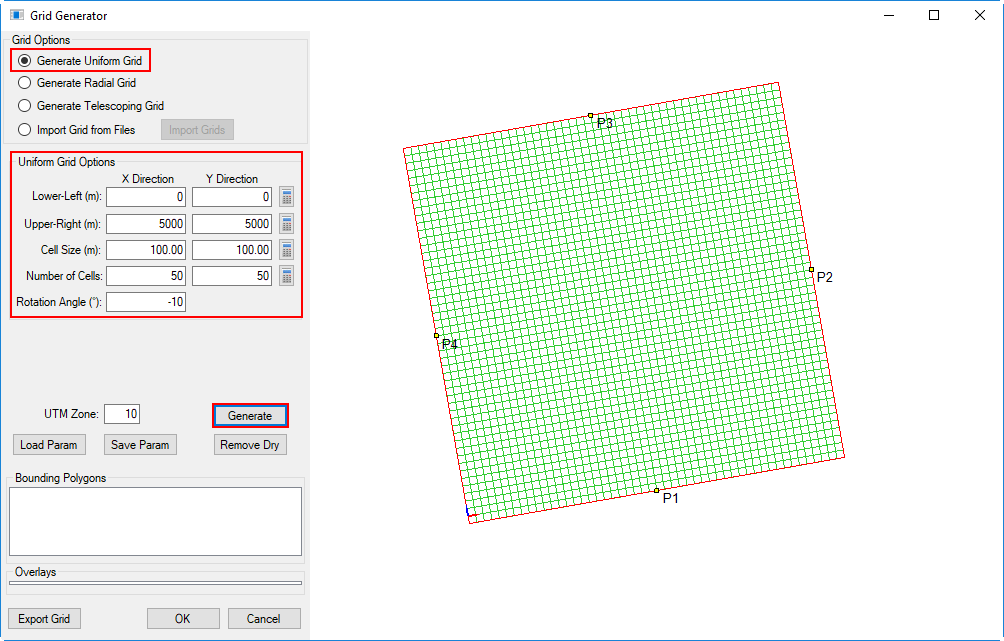
Figure 4. Generate Uniform Grid.
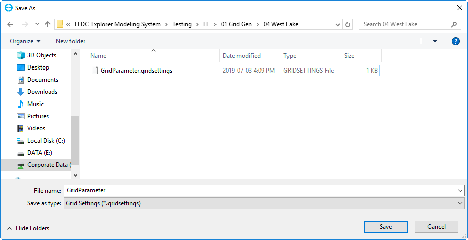
Figure 5. Save parameters.
To restrict the size of the domain use a bounding polygon, which is effectively serves as a shoreline. RMC on the Bounding Polygons text box and select Add Files. The Open form appears, and the user should select the file or files needs then click Open button as shown in Figure 6.
The polygon will be loaded and the Lower-Left, Upper-Right coordinates will be updated. The user now can generate a grid based on either cell size or the number of cells by clicking the Generate button. It is also possible inverse the selection, or remove the cells which are outside of the bounding polygon, by clicking the Remove Dry button as shown in Figure 7.
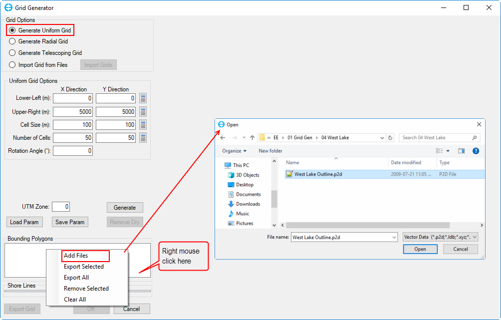
Figure 6. Load bounding polygon file.
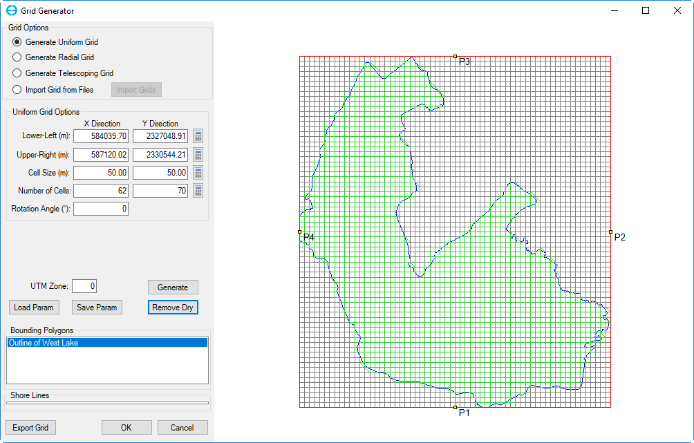
Figure 7. Grid generation by using bounding polygon.
Once the grid is generated, the user can save the grid by clicking the Export Grid button. The grid can be exported as *.CVL or *.GRD format. Click the OK button to finish generating the uniform grid.
After clicking OK button, the tool returns to the interface shown in Figure 1. Select the disk symbol or Save Model under File from the interface to save an EFDC+ model for this grid as shown in Figure 8. The files that saved are shown in Figure 9 and can be loaded by EE10.
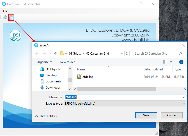
Figure 8. Save EFDC Model for generated grid.
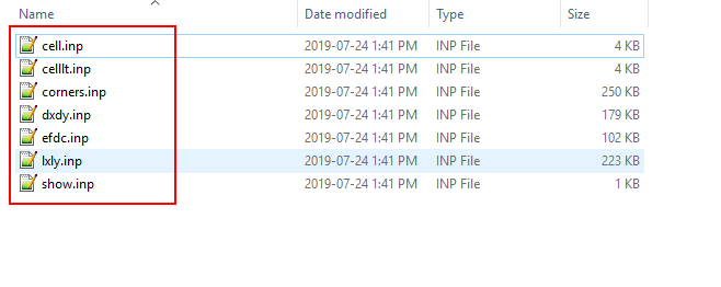
Figure 9. Files of EFDC Model save out.